Search

32-Bit Quadrature Counters
(24; 28; 38; 48 Pins)
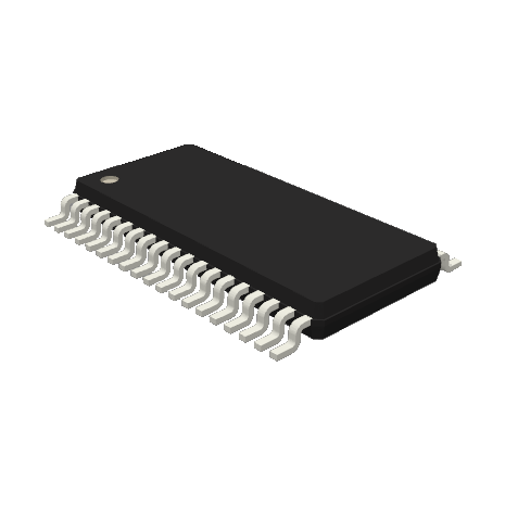
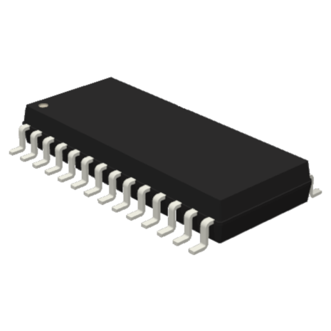
LS7766SO-S, LS7766SO-TS, LS7766SO, LS7766SH-TS, LS7766DO-S, LS7766DO-TS, LS7766DO, LS7766DH-TS

Category: Incremental Encoder Interface, Counters

Status: In Production

Stock Availability: DIP, SOIC, TSSOP

All of our Standard Products are RoHS Compliant

For pricing and availability, you may contact us, or request a quote. Most of our standard parts are available for purchase on Digi-Key, and through our Distributors.

Features:

• Direct interface with Incremental Encoders
• 40MHz(5V). 20Mhz(3.3V) Quadrature Clock Frequency
• Programmable I/Os for Index and Marker Flags
• Separate mode-control registers for each axis
• Sets of 32-bit counters, input registers, output registers, comparators and octal status registers for each axis
• Digital filtering of input quadrature clocks
• Pin selectable 3-state Hex / Octal bus
• SD / DO = Single-axis / Dual-axes Octal I/O Bus
• SH / DH = Single-axis / Dual-axes with pin selectable Hex / Octal I/O Bus
• 3V to 5.5V Operation

Description:

The LS7766 consists of two identical modules of 32-bit programmable up/down counters (CNTR) with direct interface to incremental encoders. The modules can be configured to operate as quadrature-clock counters or non-quadrature up/down counters. In both quadrature and non-quadrature modes, the modules can be further configured into free-running, non-recycle, modulo-n and range-limit count modes. The mode configuration is made via two 8-bit read/write addressable mode control registers, MCR0 and MCR1. Data can be written into a 32-bit input data register (IDR), organized in addressable Word segments using the 16-bit IO bus or in byte segments using the 8-bit IO bus. The IDR can be used to store target encoder positions and compared with the CNTR for generating marker flags when the CNTR reaches the target value. A 32-bit digital comparator is included for monitoring the equality of the CNTR to the IDR. Snapshots of the CNTR value can be stored in a read-addressable 32-bit output data register (ODR). The ODR can be read in Word segments or byte segments in accordance with the selected bus width. Data transfers among the registers and various register reset functions are performed by means of a write-addressable 8-bit transfer control register (TCR). A read-addressable 8-bit status register (STR), stores the count related status information such as CNTR overflow, underflow, count direction, etc.
Code
Package
Notes

P/N

RoHS Compliant Standard plastic DIP

1, 2, 3

P/N – S

RoHS Compliant Standard SOIC

1, 2, 3, 4

P/N – SW

RoHS Compliant Widebody SOIC option

1, 2, 3, 4

P/N – S14

RoHS Compliant 14-pin SOIC version of 8-pin part

1, 2, 3, 4

P/N – TS

RoHS Compliant TSSOP

1, 2, 3, 4

P/N – TS24

RoHS Compliant 24-pin TSSOP version of 20-pin part

1, 2, 3, 4

Example: LSxxxx-TS = the LSxxxx in the RoHS Compliant TSSOP package-type

Note 1: See Table for package body widths

Note 2: Package outline drawings conform to JEDEC standards

Note 3: Packages shipped in anti-static tubes

Note 4: Tape and Reel option available. Contact factory for details

ADDITIONAL ORDERING OPTIONS:

Probed Wafers (P/N-PW), Waffle Packed Die (P/N-WP)

Package Body Widths
# of Pins
P/N, -C, -CM
mils
-S
mils
-SW
mils
-TS
mils

8

300

150

14

300

150

173

16

300

150

300

173

18

300

300

20

300

300

173

24

600

300

173

28

600

300

173

38

173

40

600

48

240

LSI/CSI