32-Bit Multi-Mode Counter with Serial Interface (14 Pins)
LS7366R-S, LS7366R-TS, LS7366R
Category: Incremental Encoder Interface, Counters
Status: In Production
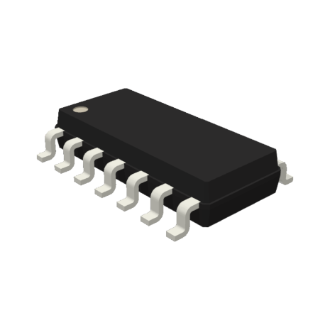
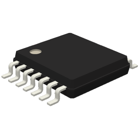
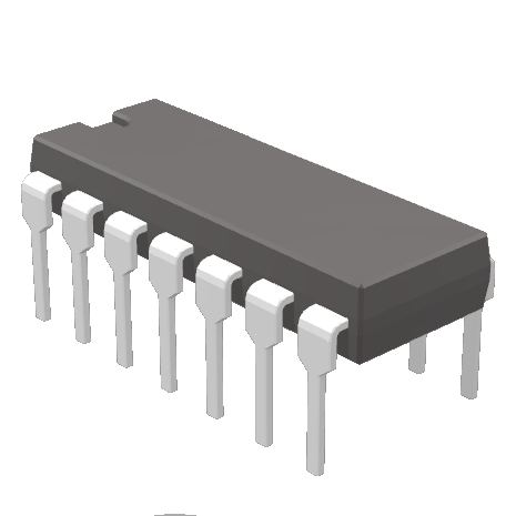
Stock Availability: DIP, SOIC, TSSOP

All of our Standard Products are RoHS Compliant
For pricing and availability, you may contact us, or request a quote. Most of our standard parts are available for purchase on Digi-Key, and through our Distributors.
Features:
• Synchronous (SPI) serial interface.
• Up to 40 Mhz Counting Frequency
• 32-bit Counter, Comparator, Input and Output Registers
• Two 8-bit registers to program functional modes
• 8-bit instruction register and 8-bit status register
• Programmable input for Counter Load
• Output Register Load or Counter Reset
• Modulo-N; Non-recycle; Range-limit or Free Running modes of up/down counting
• 8-bit, 16-bit, 24-bit and 32-bit Programmable configuration
• 3V to 5.5V Operation
Description:
LS7366R is a 32-bit CMOS counter, with direct interface for quadrature clocks from incremental encoders. It also interfaces with the index signals from incremental encoders to perform variety of marker functions.
For communications with microprocessors or micro-controllers, it provides a 4-wire SPI/MICROWIRE bus. The four standard bus I/Os are SS/, SCK, MISO and MOSI. The data transfer between a micro-controller and a slave LS7366R is synchronous. The synchronization is done by the SCK clocks supplied by the micro-controller. Each transmission is organized in blocks of 1 to 5 bytes of data. A transmission cycle is initiated by a high to low transition of the SS/ input. The first byte received in a transmission cycle is always an instruction byte, whereas the second through the fifth bytes are always interpreted as data bytes. A transmission cycle is terminated with the low to high transition of the SS/ input. Received bytes are shifted in at the MOSI input, MSB first, with the leading edges (high transition) of the SCK clocks. Output data are shifted out on the MISO output, MSB first, with the trailing edges (low transition) of the SCK clocks.
Read and write commands cannot be combined. For example, when the device is shifting out read data on MISO output, it ignores the MOSI input, even though the SS/ input is active. SS/ must be terminated and reasserted before the device will accept a new command.
The counter can be configured to operate as 1, 2, 3 or 4-byte counter. When configured as an n-byte counter, the CNTR, DTR and OTR are all configured as n-byte registers, where n = 1, 2, 3 or 4. The content of the instruction/data identity is automatically adjusted to match the n-byte configuration. For example, if the counter is configured as a 2-byte counter, the instruction “write to DTR” expects 2 data bytes following the instruction byte. If the counter is configured as a 3-byte counter, the same instruction will expect 3 bytes of data following the instruction byte.
Following the transfer of the appropriate number of bytes any further attempt of data transfer is ignored until a new instruction cycle is started by switching the SS/ input to high and then low. The counter can be programmed to operate in a number of different modes, with the operating characteristics being written into the two mode registers MDR0 and MDR1. Hardware I/Os are provided for event driven operations, such as processor interrupt and index related functions.
Code
Package
Notes
P/N
RoHS Compliant Standard plastic DIP
1, 2, 3
P/N – S
RoHS Compliant Standard SOIC
1, 2, 3, 4
P/N – SW
RoHS Compliant Widebody SOIC option
1, 2, 3, 4
P/N – S14
RoHS Compliant 14-pin SOIC version of 8-pin part
1, 2, 3, 4
P/N – TS
RoHS Compliant TSSOP
1, 2, 3, 4
P/N – TS24
RoHS Compliant 24-pin TSSOP version of 20-pin part
1, 2, 3, 4
Example: LSxxxx-TS = the LSxxxx in the RoHS Compliant TSSOP package-type
Note 1: See Table for package body widths Note 2: Package outline drawings conform to JEDEC standards Note 3: Packages shipped in anti-static tubes Note 4: Tape and Reel option available. Contact factory for details
ADDITIONAL ORDERING OPTIONS: Probed Wafers (P/N-PW), Waffle Packed Die (P/N-WP)
Package Body Widths
# of Pins
P/N, -C, -CM mils
-S mils
-SW mils
-TS mils
8
300
150
–
–
14
300
150
–
173
16
300
150
300
173
18
300
300
–
–
20
300
300
–
173
24
600
300
–
173
28
600
300
–
173
38
–
–
–
173
40
600
–
–
–
48
–
–
–
240