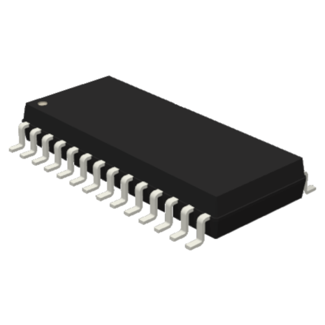
LS8292 and LS8293 are stepper motor controllers with selectable resolutions from Full to 1/32 step. There are four phase drive outputs and two inhibit outputs for controlling 2- phase bipolar or 4-phase unipolar motors. These outputs are designed to drive two external H-bridge drivers for bipolar motor windings or four external transistors for center-tapped unipolar motor windings. These outputs can also be configured to drive discrete external transistors for bipolar motor windings. A lookup table sources the PWM duty cycle digital data for the two motor windings corresponding to the step sequence. Two internal DACs convert the PWM data to analog voltages as percentages of the reference voltage applied at the Vref input. Currents through the motor windings are monitored at the SENSE inputs as voltage drops across fractional-Ohm resistors in series with the H-bridge drivers. Upon turning on a PWM drive, when the voltage at the SENSE input reaches the DAC reference level, the PWM output is switched off for remainder of the cycle. The PWM cycle is fixed at Tpwm = 256/fc, where fc is the clock frequency at the XTLI input. The PWM cycles for the two drives are started simultaneously but terminated separately per individual DAC references.
An input is provided for the holding torque state at lower winding current in the motor idle state. The holding-torque current level is adjusted with a separate reference voltage applied at the Vrefh input. The Vrefh is automatically switched in if the motor idles for a programmable specified delay following a micro-step.
PWM chopping can be applied either to the PHASE or to the INHIBIT outputs. The chopping mode affects the manner in which the winding current decays during a PWM cycle. There are four selectable decay modes: Fast-decay, Slowdecay, Single-mixed-decay and Dual-mixed-decay.
In the Fast-decay mode the diagonal high side and low side transistors of the H-bridge are both turned off during the PWM off period. This causes the inductive current to be dissipated through the bypass diodes in a direction opposing the motor supply voltage resulting in fast decay.
In the Slow-decay mode the low side transistor of the H-bridge is turned off keeping the high side transistor on during the PWM off period. This causes the inductive current to re-circulate through the high side transistor and diode loop. The current decays slowly because of the low loop voltage. The Slow-decay can be useful for motors that do not store enough energy in the windings leading to an average current too low for any useful torque.
In the Single-mixed-decay mode, slow and fast decays are combined in the following way:
When the motor is idle, slow decay is applied to both windings to guarantee lowest current ripple in a holding state.
When the motor is stepping, if the step requires the current in a winding to decrease, fast decay is applied to the winding for a programmable duration followed by slow decay. If the step requires the current in a winding to increase, slow decay is applied to the winding.
One of six stepping modes can be selected by two input pins: Full, 1/2, 1/4, 1/8, 1/16 and 1/32. An internal oscillator generates the system clock and sets the PWM period. The oscillator pin can also be driven by an external clock. Other available inputs are for step command, direction control, resetting to home position, disabling the H-bridge drives, SENSE input blanking delay control and fast to slow switching delay control in the mixed decay modes.


